Regular readers will be aware of my contant battle with noise, both natural (QRN) and man-made (QRM) and some of my past attempts to mititage them. These include the purchase of a Wellbrook loop and both a WiMo QRM Eliminator and an MFJ-1026.
Both the WiMo and MFJ are quite capable at "nulling-out" noise sources but as one of my primary interests is 80m contesting, they just take too long to setup for each signal which really rules them out unfortunately. I had also mounted the Wellbrook on a cheap "TV" rotator but found that the nulls didn't seem to be deep enough for me to effectively remove the most persistent of noise sources that I encounter in my heavilly developed QTH.
Sometime ago I became aware of Chavdar LZ1AQ and his designs for an active loop antenna amplifier (AAA-1) but what specifically interested me was the combination of multiple AAA-1 amplifiers with a variable delay line (VDL-1) which allows you to effectively steer the "array" with simple controls. So I decided to purchase a VDL-1 and 3 x AAA-1 and see if I could build a steerable array.
I spent a considerable amount of time reading the wealth of information available Chavdar's website http://active-antenna.eu which is a great resource for anybody who is interested in building anything from a single receive loop to a full steerable array.
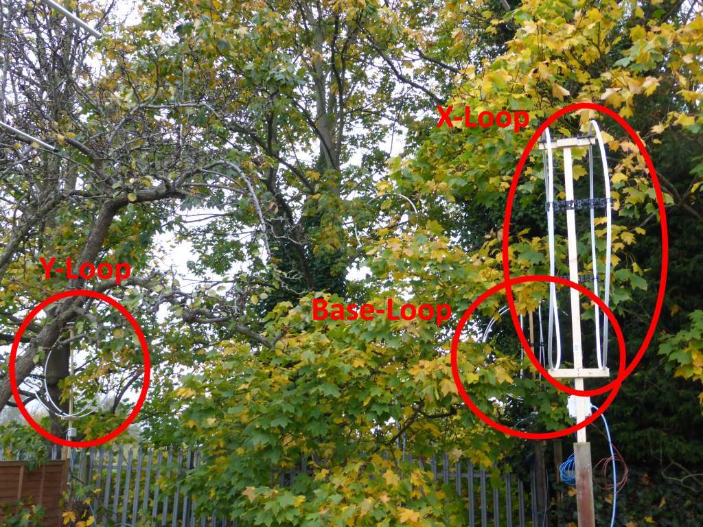
 The array comprises of 3 seperate 1.27m diameter dual-loops (one being a pair of dual-loops) arranged in an "L" shape (named X, Y and Base). The loops themselves are constructed out of 16mm Pert-Al-Pert underfloor heating pipe. This very flexible pipe contains a layer of aluminium sandwiched between two layers of plastic. The recommended termination method is to crush the end of the pipe and then melt-off the top plastic layer with a soldering iron. This proved quite effective and apart from a destroying a perfectly good soldering iron tip, was pretty straight-forward.
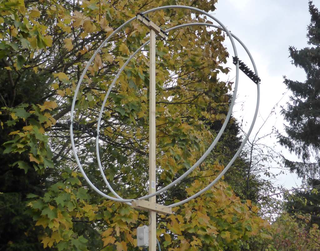
As you can see from the picture, each loop is actually made-up of two 4m lengths of pipe separated by 250mm. I used the plastic spacers designed for this pipe as 'spreaders' but any method would work. I used lengths of 19mmx38mm planed timber for the support, I didn't think it was necessary to use anything thicker as the loop is so light with very little wind-loading. The box at the bottom contains the AAA-1 amplifier.
Both the X and Y loops are of identical construction. I decided to construct the array in "dual-mode" as this allows them to operate either as loops or dipoles, each loop also has a short (2m) length of cable which forms the bottom leg of a short vertical dipole (with the loop forming the upper leg) although in practice I have found this mode of operation to be far too noisy to be particularly usable.
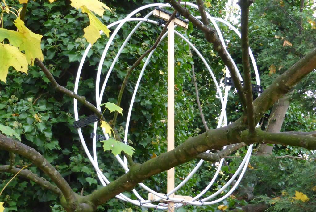
The Base loop is constructed slightly differently as it is actually a pair of loops mounted orthogonally (at right-angles to each other)
All of the loops have dedicated AAA-1 amplifiers which are connected into the VDL-1 (delay line) box with shielded CAT5/6 cable. I had a box of CAT6a cable which has individually foil screened pairs but any shielded CAT5 or better cable is fine. The connections between the 3 x AAA-1 amplifiers and the VDL-1 is critical though as they must all be exactly the same length (LZ1AQ also recommends if possible that all cables should be from the same batch/drum as numbers of twists etc. can have an effect). The loops themselves must also be mounted the same distance apart from each other.
Loop position and therefore cable length will obviously be dictated by available space, my garden is just under 7m wide so that was the maximum spacing that I could use. LZ1AQ recommends a space of between 9 and 15m and says that lower spacing will still work but will result in lower signal levels and higher noise-floor. This does increase the directional properties of the array though! Once the space between loops is decided, you can set the delay parameters using the formula T=D*3.34 (where T is the delay time in nano-seconds and D is distance between loops in metres). This is achieved with a block of jumpers within the VDL-1.
There is quite a lot of wiring and therefore plenty of scope for errors, once wired and tested it was time for some "on-air" testing.
I have not used the array in a contest situation yet but initial results are very favourable with the ability to "steer" the array away from some quite loud noise sources and on 160m, 80m and 40m it seems to perform better than the Wellbrook loop but I need to do some proper A/B comparisons.
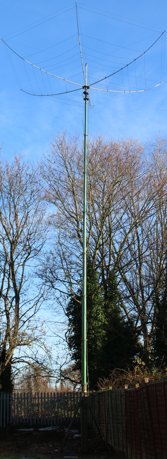
The final layout of the loop array is pictured below, it is quite effectively masked by the covering of large trees at the end of my garden! The Wellbrook is just visible in there as well. Obviously the proximity to the metal boundary fence at the end of the garden isn't ideal but it doesn't seem to effect it that much.
.